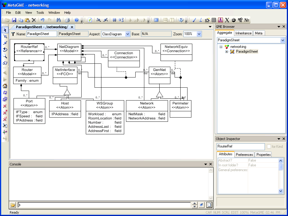
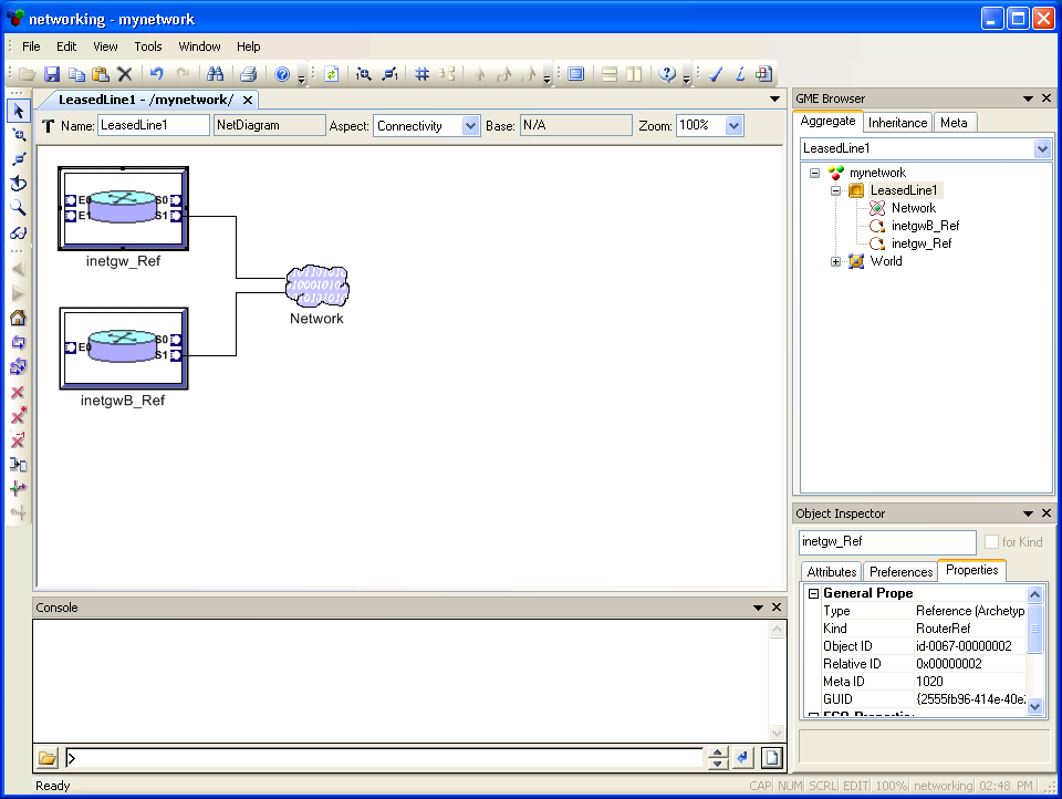
Fig 4.1 Implementing cross-hierarchy relationships with references
Solution #1: using NetDiagram references
Introduction to Lesson 4
4.1 References
4.2 Sets
Lesson 1 introduced three of the primary modeling entities: atoms, models and connections. Obviously these concepts (or functionally equivalent ones) are essential for modeling even the simplest systems. Their use in more complex systems was demonstrated through the hierarchical network modeling application of Lesson 2 .
Still, there are countless situations that would be cumbersome and/or impossible to model using only the concepts seen so far. Fortunately, GME supports a few additional concepts that add to its descriptive power, giving it a much wider range of modeling capabilities.
Consider the following problem in the networking domain.
We have an ambitious modeling project which describes a complex, hierarchical
network. The root model is the Internet backbone. The next level contains the
continents: Europe, North America, Asia, etc. Within each continent there is a
level consisting of country networks, which have an optional level of domestic
regions (U.S. states, for example). Under those, each Internet Service Provider
has a separate NetDiagram, and each ISP client with more than one PC has a
separate NetDiagram on the lowest level.
Imagine a situation in which two companies, ZebraStripes PLC (a client of the
ZimbaNet ISP in Zimbabwe) and PantherSpots Corp. (a client of BurmiNet in
Burma), recognize that they are doing so much business with each other that the
added bandwidth of a direct leased line between them would significantly improve
their synergy. (See Figs 4.1 - 4.3.) A leased-line connection is typically
configured as an IP network between two router ports with only two addresses
used at either end of the line.
Where will this leased-line network be inserted in the hierarchy? How can we
represent the idea that these companies connect to a network that spans two
continents?
If we follow the rules set forth in Lesson 2, our
solution will be to find the lowest point in the hierarchy where both companies
are contained, insert the new network there, and use a chain of perimeters along
the hierarchy levels to make the network accessible in both companies. Since the
lowest point in this case is "World", the network should be placed there. A
perimeter is added to each level (continent, country, ISP, company), and the
perimeters are connected by NetworkEquiv relationships, so that the perimeters
in both company diagrams are "wired" to the new Network object in "World".
Clearly, this action will add at least 8 extra Perimeter objects to our model.
Also, we must put the new Network in the highest level of the hierarchy. As the
number of leased intercontinental data lines continues to grow, the "World"
diagram quickly becomes too large to handle. Other plausible scenarios, such as
ISPs or other distribution centers with data lines to more than one continent or
country, only exacerbate the problem. These situations are common; many European
ISPs have their own direct leased-line connection to the U.S.
Translating all this into modeling terminology, the problem is that we do not yet have a way to represent relations that cross hierarchies. Connections, our only relation so far, can only connect objects when they are in the same NetDiagram or when one of the diagrams is the immediate child of the other. References in GME are provided to overcome this exact limitation. As the name implies, a reference is an object that represents another object somewhere (possibly far away) in the modeling hierarchy. When a reference is created, it is associated with a referred object, which it represents (unless it is a NULL reference).
For the networking example, references offer us several solutions for the problem described above:
Even though hierarchy is a very useful concept, there are situations in which it cannot efficiently model a system on its own. Most systems have components which cannot be fully isolated within the hierarchical containment. Also, sometimes there are a few objects that belong to multiple locations in the hierarchy (e.g. a secretary working for two different departments). Therefore, techniques are needed to refer to remote objects from within the diagrams. References are objects that represent other objects, typically located somewhere else in the modeling hierarchy. References provide the ability to span the hierarchy without "breaking" it and voiding its convenient properties (each object has a single parent, traversing the tree visits each node exactly once, etc.).
References are such powerful tools partly because different modeling scenarios use references in different ways:
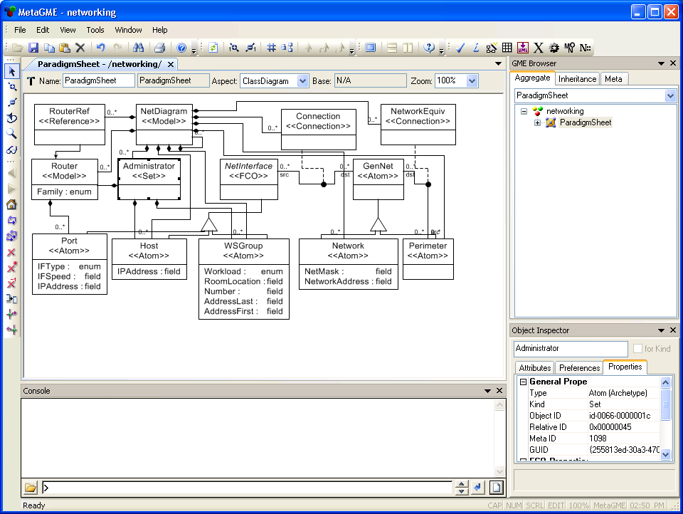
4.1.1 Defining and working with references
We will now update our networking metamodel so that we can create models with Router references, as shown in Fig 4.2 and Fig 4.3. (The same paradigm can be used for both models.)
Now let's build a model with a leased-line connection between two companies,
using the technique shown in Fig 4.3.
References add a significant amount of power to GME. All real-world GME
applications use references; some applications use them extensively. Sometimes
they are used as aliases, sometimes as pointers, and sometimes they simply
represent a generic association, where the concept of a reference seems to be
more intuitive than a connection. This is often the case when the real-world
object is a kind of pointer by itself: a Table of Contents Entry in the model of
a book, for example, or a mailbox for a recipient in the model of a mail
forwarding system. When working with GME, feel free to use references for any
purpose and to define any type of semantics for them.
Connections and references are two different types of associations in GME. But they are often used together, as in the example above: the reference locates a remote object so that a connection can be established between two objects which are not visible together from any container.
It is worth noting that many other modeling tools do not have anything resembling a reference, which makes the concept even more remarkable.
We have already seen two different types of associations in GME: connections and references. Together, they have the power to describe any situation. Sometimes, though, these associations are not the most convenient option. Let's see if we can use them for the following example:
Mid-size companies have several IT administrators. Each administrator is usually responsible for a couple of machines. Important machines may have several administrators (and some of them work for years after the only person with administrator access leaves the company...). We want to extend the network model to include information on administrators and their responsibilities.
Let us introduce a new object, "Administrator". How shall we represent the "administers/administered by" relationship?
One way to understand sets is to compare them to the way that aspects are
specified in the metamodeling environment. In that situation, sets represent
meta-aspects. The "lasso" selection mode used when dealing with aspects
( ![]() ) also provides a way to specify set
memberships.
) also provides a way to specify set
memberships.
This example shows that the concept of sets is not as indispensable as that of connections or references. Sets can usually be replaced by connections. You should regard sets as an alternate association technique that supplies greater convenience in many situations.
(Please note that the current version of GME supports sets in a rather limited way: the set and its members must be siblings, and objects represented by references cannot be added to the set. These limitations will be eliminated in future releases.)
4.2.1 Defining and Working with Sets
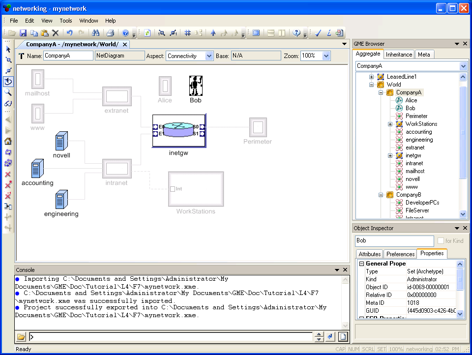
Let us extend the network modeling environment by adding administrators, as seen above.
|
Admin.bmp |
Now that we have completed Lesson 4, all members of the FCO family (models,
atoms, connections, references, and sets) have been introduced. Additional
GME concepts will be discussed in future lessons. These concepts are just as
important to the modeling environment, but are not FCOs.
| << Previous Lesson | Complete List | Next Lesson >> |