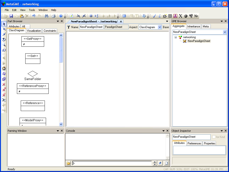
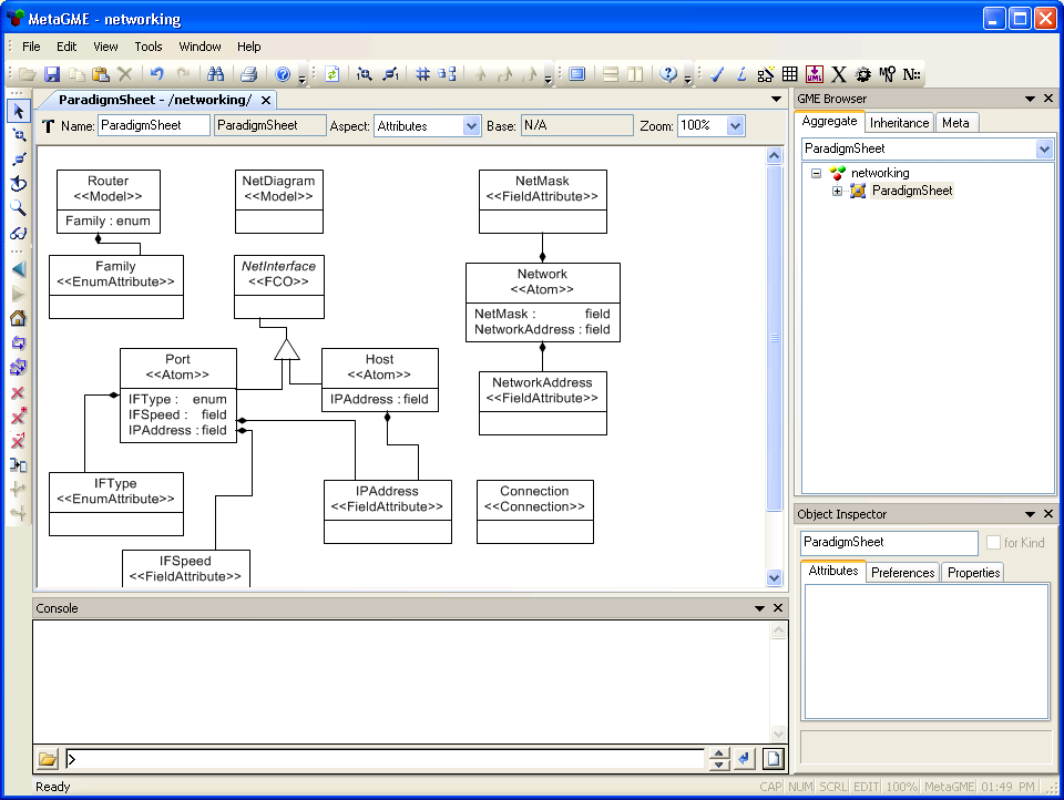
Fig 1.1 GME metamodel with an empty paradigm sheet
Introduction to Lesson 1
1.1 GME and the modeling process
1.2 Creating a metamodel
1.3 Creating the first model
1.4 Enhancing the metamodel and the model icons
In this first lesson, you will configure GME to allow the drawing of basic diagrams for a specific application domain. Later lessons will show you how to extend the project with more advanced features.
The application domain throughout this tutorial is that of networking systems: routers, networked computers, and other devices, as well as the connections between these devices. Your application domain is probably quite different from this one, but looking at a specific domain as an example is probably the best way to help you identify the main steps of modeling and learn the techniques of customizing GME. There are some sections that describe the details of networking, and serve as "theoretical backgrounds" for accomplishing a certain task in GME in a particular way. Those sections appear in red italics. If you are not familiar with networking, you may find them irrelevant or hard to understand. Feel free to skim or even skip them, and focus on the rest of the tutorial, which deals with the more practical aspects of GME.
This tutorial provides enough information to give the average user a well-developed understanding of GME, without having to rely on extra documentation. Of course, to gain a deeper understanding of GME and to learn all of its features, you will need to consult the GME Users Manual as well.
GME is a generic, configurable modeling environment. In other words, the configuration of GME is not an option; it is the first step that must be taken before anything meaningful can be done with it. The configuration process itself is also a form of modeling - the modeling of a modeling process. This is called metamodeling. The output of the metamodeling process is a compiled set of rules, the paradigm, that configures GME for a specific application domain.
Does everyone need to be a metamodeling expert to use GME? Of course not. Normally, only a few people participate in the metamodeling process. By contrast, there are numerous users of the configured environment. The users do not need to know much about metamodeling; what they see is a graphical tool with editing capabilities that is already customized for their domain. The main advantage of model-integrated computing is that the work of the users is guided by the modeling environment.
This tutorial is written for those who are interested in metamodeling and customization. The majority of the tutorial deals specifically with metamodeling issues; examples of customized environments are usually explained in much less detail. Remember, the metamodeling environment itself is also based on GME. So while acting as a metamodeler, you are also a user of the customized environment of GME, based on its meta-paradigm. By the time you begin to build models, you will have already had plenty of practice simply by using the metamodeling environment!
The first thing that a metamodeling expert needs is a specification (or at least some vague idea) of the modeling application to be implemented. This typically comes in a natural-language description. As an example, the proposed network modeling application is described below:
"We want to create networking diagrams. The diagrams will contain routers. Each
router has several router-ports. We also have hosts (e.g. servers). We want to
connect router-ports and hosts to form networks.
"Routers are identified by name and family. Name is a string, family is one of
the following: "C16xx", "C25xx", "C36xx", or "Linux" [i.e. we have Cisco and
Linux routers]. Ports are identified by portname, IP address, speed (in kbps),
and type (which is either "HDLC", "PPP" or "Ethernet").
"Hosts are identified by name and address (for now, they all have a single
Ethernet port). Networks are identified by a network address and a netmask."
1.1.2 The modeling approach
We now have a description of the concepts to be modeled using the GME metamodeling environment. The modeling technique we are using is the well-known and widely accepted Unified Modeling Technology, especially a specific subset called UML Class Diagrams.
The most basic step in the metamodeling process consists of determining two things: the entities used by the model, and the relations between them. Information used to identify and qualify certain entities and relations will be assigned to them as attributes. Metamodeling, in a nutshell, is the mapping of specification concepts onto entities, relations and attributes.
We have been given the specification. Now let's describe the modeling paradigm:
1.1.3 Generic modeling concepts in GME
GME supports a set of generic modeling concepts that are variations of the UMT entities, relationships, and attributes. The differences reside partly in the nomenclature and partly in additional features, semantics, and constraints which are expected to guide and simplify the metamodeling process.
Now that the theoretical process of metamodeling has been described, let us see how the process is conducted in practice. You can follow the instructions below to create a metamodel for the networking application example, or you can adapt the instructions for a separate modeling problem and begin implementing your own customized GME environment.
1.2.1 Creating a new metamodeling project
Start GME, and select "File/New Project...". A dialog box pops up to let you choose the paradigm the new project will be based on. Since we are creating a metamodel, the paradigm will be "MetaGME". Select it and press the "Create New..." button. The next dialog asks you to specify the data storage. Simple models are usually stored in project files.
After clicking "Next", a file dialog asks you to name a project file. The standard extension is ".mga". Specify a name (like "networking.mga") and press OK.
GME has now created and opened an empty project. The project is named "networking" and is associated with the MetaGME paradigm, the GME built-in metamodeling paradigm that configures the environment for use as a metamodeling tool. Note that the project is not completely empty: it contains a root folder, also named "networking".
1.2.2 Creating a paradigm sheet.
Right click on the root folder in the Browser window (the one usually docked at the right side), and select the single option "ParadigmSheet" within the "Insert New Model" option. A new object named NewParadigmSheet is created under the root. Double click to open it. A white window appears in the user area (Fig 1.1). This window displays the empty contents of the NewParadigmSheet model, which serves as the all-enclosing drawing board for your class (i.e. entity) diagram. The header of the window contains the following:
1.2.3 Defining entities.
Make sure the current aspect is "ClassDiagram". The Part Browser, a small window in the lower left portion of the program, displays the selection of objects that can be inserted into the model in its current aspect. Drag a "Model" from the Part Browser onto the main window. This will be the entity that represents a router. Give it the name "Router" by selecting it and clicking the topmost input field in the Attributes/Preferences/Properties window (located in the lower right section of the program). The generic GME concept "model" - indicated by <<Model>> in the defining class - is the stereotype for routers. Therefore, since routers are models, they can contain other objects (i.e. router-ports).
Now create three <<Atom>> classes, and name them "Port", "Host" and "Network". The relations will be represented by connection entities, so create a <<Connection>> object and let it keep the default name "Connection". (This is an example of an overloaded name: a connection entity represents a relationship which happens to be called "Connection" in the networking paradigm.)
We have created five entities so far, but we still need a couple more. First, we must add something to act as a base container for the routers, networks, hosts, and their relations. This will be a <<Model>> named "NetDiagram"; add it to the metamodel.
Now we need just one more class: a generic entity that represents "anything that can be directly connected to a network" (i.e. router-ports and hosts). The modeling environment should not allow this object to be directly created. Therefore, it must take the form of an abstract baseclass for router-ports and hosts. Create it as an <<FCO>> and name it "NetInterface", because it essentially represents anything that incorporates a network interface.
Our paradigm sheet now contains all seven necessary entities: two models, three atoms, a connection, and an FCO.
1.2.4 Generalization, containment, and association.
The next step is to indicate relationships between entities. Relationships are
represented by lines, so switch the editor mode to "Add Connection" ( ![]() ).
).
Let us start with NetInterface. We want to show that Ports and Hosts are
NetInterfaces; in other words, they implement NetInterface. The UML
notation for this is a line connecting the subclasses to the baseclass, passing
through a small triangle that points to the baseclass. In the Part Browser,
locate a small triangle named "Inheritance" and drag it onto the user area.
Since we won't refer to this object directly it
does not need to have a specific name. Click NetInterface, and make sure the cursor is changed to ![]() . Click the triangle, and VOILA! -
the first connection is drawn! Now connect the triangle to the subclasses. Do
this by clicking the triangle first; this tells GME which object is the base
class and which are the derived classes in the inheritance. We now have a UML
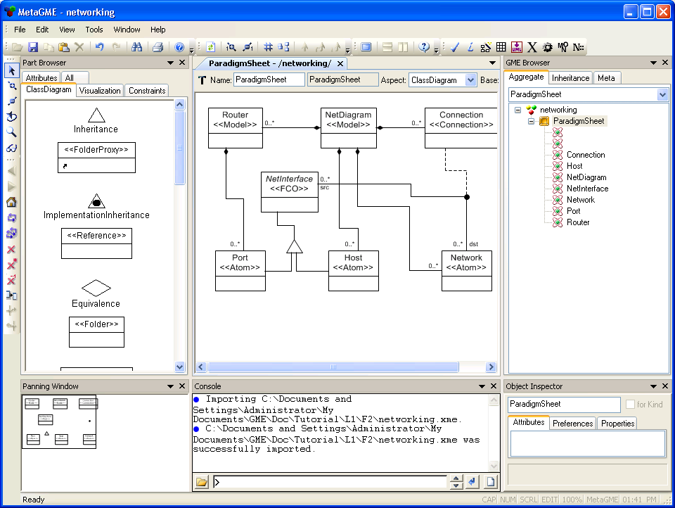
generalization relationship, just like the one shown in Fig 1.2.
. Click the triangle, and VOILA! -
the first connection is drawn! Now connect the triangle to the subclasses. Do
this by clicking the triangle first; this tells GME which object is the base
class and which are the derived classes in the inheritance. We now have a UML
generalization relationship, just like the one shown in Fig 1.2.
Routers contain ports; this will be the second type of relationship we
implement. The UML notation for containment is a line connecting an object to
its container, with a small black diamond on the "container" end of the line.
Containment is easier to draw than inheritance; no triangles are involved. Just
click the contained object first (remain in "Add Connection" mode, ![]() ), and the container second.
Whenever your coursor is above an object that can be a candidate for a
connection, the border of the object gets red. Moreover, when the cursor
is near one of the side lines of the box, a little red square will appear in the
midpoint of the line. This indicates that the user is able to enforce the
location of the connection line attached to the box. If you chose one of the
side lines to create the connection, GME will always draw the connection
from that side, even if the object is moved from its place. If you simply click
in the middle of the object, GME will always try to find the best routing
for drawing the line representing the connection. Near
the end connected to the contained class, the multiplicity "0..*" is
displayed. We will leave this alone for now.
), and the container second.
Whenever your coursor is above an object that can be a candidate for a
connection, the border of the object gets red. Moreover, when the cursor
is near one of the side lines of the box, a little red square will appear in the
midpoint of the line. This indicates that the user is able to enforce the
location of the connection line attached to the box. If you chose one of the
side lines to create the connection, GME will always draw the connection
from that side, even if the object is moved from its place. If you simply click
in the middle of the object, GME will always try to find the best routing
for drawing the line representing the connection. Near
the end connected to the contained class, the multiplicity "0..*" is
displayed. We will leave this alone for now.
Do not forget that there are more containment relationships to be defined: Routers, Hosts, and Networks are contained by NetDiagrams. GME also requires that relationships (or connections) are contained somewhere, so add a containment relationship between Connections and NetDiagrams as well.
If the containment lines in our metamodel look like those in Fig 1.2, we are ready to move on to the third and final type of relationship: associations.
We have already defined the association class, "Connection", but we still need
to indicate what objects this relationship can associate. This is a ternary
relation between the association class and the two endpoints of the association,
so another helping object, a small black dot ( ![]() ), must be used. Drag it onto the diagram from the Part Browser.
The connection source will be router-ports and hosts. Only one
source can be specified for each connection, but we can get around this by using
the common baseclass, NetInterface, to represent both sources. Connect
NetInterface to the connector dot. The line displays "src" as the role,
and "0..*" as the multiplicity at its NetInterface end..
), must be used. Drag it onto the diagram from the Part Browser.
The connection source will be router-ports and hosts. Only one
source can be specified for each connection, but we can get around this by using
the common baseclass, NetInterface, to represent both sources. Connect
NetInterface to the connector dot. The line displays "src" as the role,
and "0..*" as the multiplicity at its NetInterface end..
Now specify the destination: first click the connector dot, and then the "Network" class. The association class, "Connection", is the third leg of the association relationship. When you connect this class to the connector dot (in any order), GME displays a window asking you to clarify the role of this relation. Select "Association Class" here.
We have now defined all three basic UML relations: generalization, containment and association (Fig 1.2).
1.2.5 A visit to the "Attributes" window
The UML class diagram looks ready, but there is still one more thing to do.
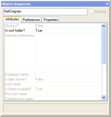
The Attributes/PreferencesProperties window is located in the lower right corner of the screen, and shows the attributes, user preferences and properties of the currently selected object. This window has three panes; select the "Attributes" tab to expose the attributes. Here is a quick list of the metaparadigm entity attributes we will encounter:
Attributes have a default value that is defined in the model's paradigm (in this case, the metamodeling paradigm). The default value is enabled if nothing else is expressly set. The name of the attribute and the value of it are displayed gray until the user changes them indicating that the attribute's default value is used. Fortunately, most default values are appropriate at this point. To practice working with attributes, we will change only one: the "In root folder?" option in the "NetDiagram" entity. We want to indicate that network diagrams can be directly created in the root folder. Follow these steps (see Fig 1.3):
As mentioned above, relation entities can also possess attributes. Although this
feature is seldom used, our metamodel happens to require attributes for a
particular containment relationship. The Attribute pane for a connection may be
opened by selecting "Attributes" from its context menu (make sure you point
exactly at the connection line). Open the Attribute pane for the "Composition"
line between Router and Port. Change the value of the "Object is a port?"
attribute to "True". This tells GME to treat Port objects as
ports of Routers; they are visible and accessible from outside the parent
model. The Attribute pane for relations also controls the association endpoint
names and multiplicities, or cardinalities. (The latter will be explained in
Lesson 6).
The metamodel's UML Class Diagram part is now complete, but the rest of the metamodel needs further adjustments. The remaining information can be entered using the other three aspects of the NewParadigmSheet: Visualization, Constraints, and Attributes. (Constraints will not be defined at this point in the tutorial, so this aspect will be skipped for now.)
1.2.6 Creating an Aspect
A model must contain at least one aspect. Switch to the "Visualization" aspect of the metamodel. (This is a good place to point out a key difference between the metamodel and the model: the visualization aspect in the metamodel allows us to define aspects for our application.) Drag an "Aspect" onto the paradigm sheet. Name it "Connectivity" to distinguish it from other aspects that we will create later.
Aspects are a type of set: the objects contained in this aspect are known
as its members. Switch to "Set Edit" editor mode ( ![]() ). Right-click the new aspect, and then include all other entities in
the diagram by left-clicking them. The result is shown in Fig 1.4.(You could include
the NetInterface abstract base class, thus you would not be required to include the
classes derived from it.)
). Right-click the new aspect, and then include all other entities in
the diagram by left-clicking them. The result is shown in Fig 1.4.(You could include
the NetInterface abstract base class, thus you would not be required to include the
classes derived from it.)
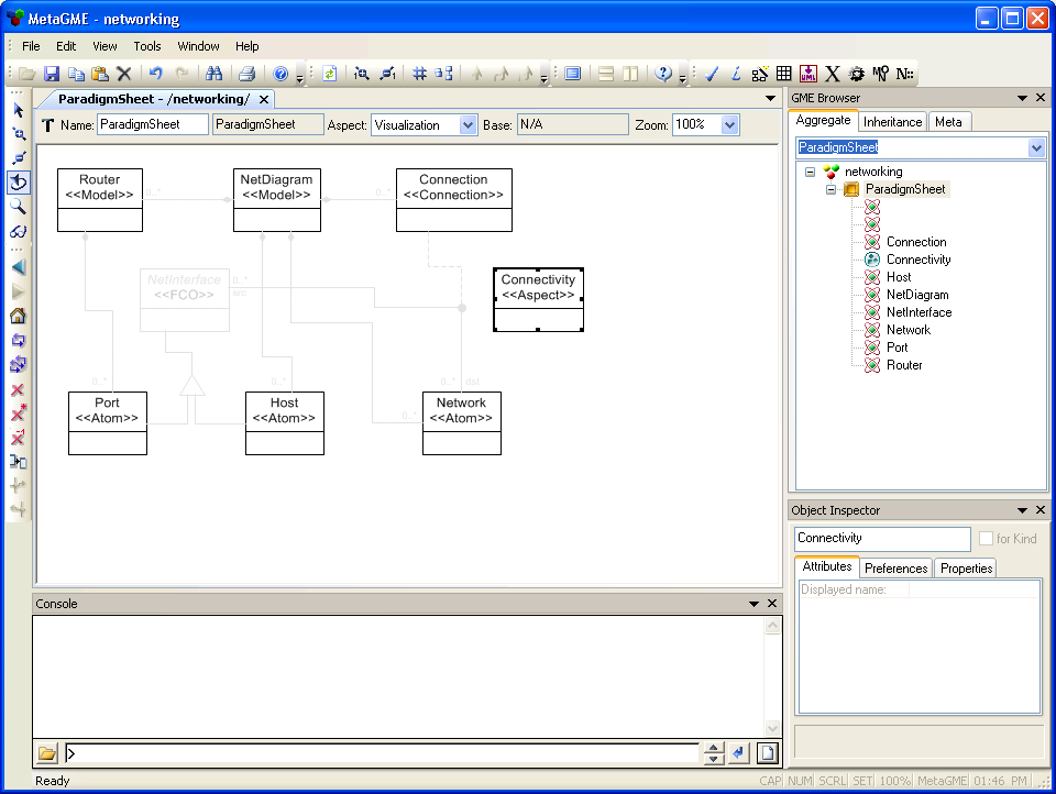
Membership in the aspect set indicates that every instance of a given
meta-entity is visible in this aspect. We must
also show that this aspect is contained in both of the models. A containment
relationship will accomplish this; switch to "Add Connection" mode, and create
containment connections from the aspect to both the Router and NetDiagram
models.
We have succesfully created an aspect! Since the model contains only one aspect, it might be difficult to understand why this step is even necessary. In Lesson 5, we will learn more about aspects and how they function in a model.
1.2.7 Specify attributes
This is the last major step! Switch to the "Attributes" aspect. (As stated earlier, constraints are not used in this lesson).
Attributes are data fields of entities. The data fields are mentioned in the specification; some examples are name, type, IP address, and speed. In the configured network modeling environment, attributes for objects will be accessed in much the same way as Fig 1.3, which shows the attributes of a UML class in the metamodel. (Make sure you understand the difference between attributes of entities that are used in the metamodel, and attributes of entities that your metamodel is expected to define!)
In standard UML class diagrams, attributes are defined in the lower half of the class rectangle. GME also displays attributes on the class diagram, but they are defined in a separate aspect. A connection relationship (which visually resembles UML containment) is used to assign attributes to classes.
Let's start by creating attributes for the Router entity:
Create the following:
1.2.8 Interpret the metamodel and install the new paradigm
Now we will convert the metamodel into a GME paradigm. Click the button
with the cogwheel icon ( ![]() ) in
the toolbar. Click "OK" on the "Configure Aspect Mapping" dialog. The next
dialog selects the location of the paradigm XML file.
) in
the toolbar. Click "OK" on the "Configure Aspect Mapping" dialog. The next
dialog selects the location of the paradigm XML file.
If there are no errors in the metamodel, the final dialog reports that the paradigm has been generated, and asks if it is to be registered. Before they are used, paradigms must be registered (the name and properties must be entered into a specific part of the Windows registry), so select "OK".
Although theoretically unnecessary, it is a good idea to save your work (with "File/Save Project") before testing the paradigm. If you are working from a database, this step is not needed, since all edits immediately persist. If you are working on file-based models, GME automatically offers to save your work when you quit the program. However, system crashes and other unforeseeable problems may still cause data loss.
Select "File/New Project..." from the menu to start a new GME project. The familiar series of dialogs appear. (This is a key feature of GME; users need only learn one process for both modeling and metamodeling.) The newly installed paradigm, "networking", should be visible in the paradigm list. Select this paradigm and choose an appropriate filename, like "mynetwork".
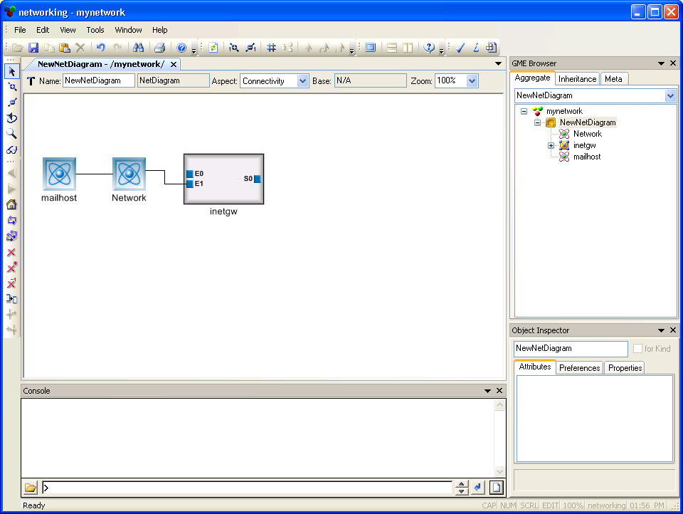
The screen of the new model looks just like Fig 1.1, except that the root
object is now "mynetwork" or whatever name you used for the file. Right click
the root object; the model available for insertion is NetDiagram. This is the
first sign of customization! Insert a NewNetDiagram, and open it. The part browser
now shows Host, Network, and Router, just as it should. Create a Host and a
Network. Give them names like "mailhost" and "localnet", respectively.
Test the connections: in Add Connection mode ( ![]() ), connect "mailhost" to "localnet". Now test the attributes:
mailhost has an IP Address, localnet has a Network Address and a NetMask. The
configured modeling environment really knows what to do!
), connect "mailhost" to "localnet". Now test the attributes:
mailhost has an IP Address, localnet has a Network Address and a NetMask. The
configured modeling environment really knows what to do!
Now let's see how Routers behave in the model. Create a router and name it "inetgw". Set its Family attribute to one of the four options: "C25xx", for example. The router needs ports, so double-click it to access its internal structure. We can now add ports from the part browser. Add three ports to this router; name them E0, E1, and S0. Place E0 and E1 on the left side of the window and S0 on the right side. Close the inetgw window; the router now has three ports. Connect E1 to "localnet".
Let's try to trick GME. Connect E0 to "mailhost". It does not work; this type of connection is not allowed by the paradigm. We cannot even connect Networks to Hosts because connections are directed by default, and connections in the reverse direction (from Network to NetInterface) are not specified.
We do not yet have any objects to connect E0 and S0 to, so leave them unconnected for now. Our first model, built for our first paradigm, looks like the one in Fig 1.6.
So far, the capabilities of the customized modeling environment are hardly enough to justify the amount of work invested in the metamodel. This is because the beginning is usually the hardest part; what typically follows is the incremental enhancement of the metamodel and the example projects. This enhancement is repeated many times, forming a cycle which includes the following steps:
First, we will have to create bitmaps (one for each object, two for ports; one large and one small). Bitmaps must be in BMP format. If you - like me - are not a good computer artist, you may use the the following bitmaps:
|
Host.bmp |
Network.bmp |
Router.bmp |
Port.bmp |
PortSmall.bmp |
Icon files may be saved anywhere, but it is a good practice to copy them to a
subdirectory named "Icons" in the directory of your paradigm file. You can find
the location of the paradigm file with the "File/Register Paradigms..." dialog.
(If the icons are stored in a different place, you must set the icon path; this
process is described below).
When creating your own bitmaps, here are some points to consider:
Re-interpret and re-register the paradigm as described above. Registering a new version of a paradigm does not delete the previously registered version(s), so existing models will continue to use the version that they were created with. New models, however, are created with the current paradigm, which is normally the most recently installed one.
It is possible to upgrade existing models to a newer paradigm in two different ways:
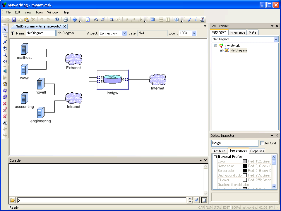
The paradigm upgrade process described above may be repeated several times to implement other modifications and to fix errors in the paradigm. Once we are satisfied with the model paradigm, we can create real diagrams, like the typical network of a small company in Fig 1.7.
| << Previous Lesson | Complete List | Next Lesson >> |